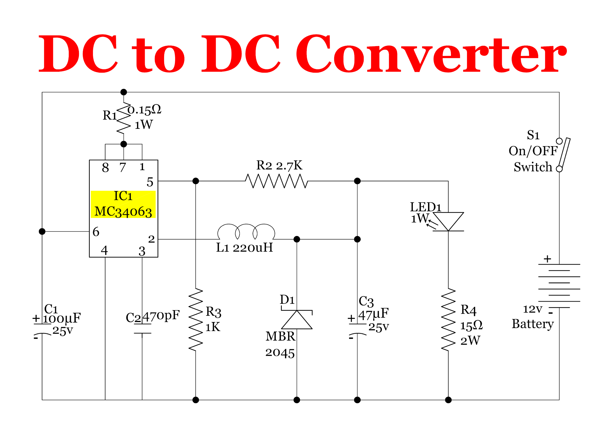
Voltage doubler dc multiplier circuits diode working circuit bridge Dc converter circuit 555 simple ic isolated using boost digital diagram transformer power output circuits timer eleccircuit transistor supply current 3 frequency to voltage converter circuits explained
12 Volt Dc Voltage Regulator Circuit Diagram Pdf - Wiring Diagram
Lm2596 voltage dc step down regulator switching circuit eleccircuit power datasheet converter ic circuits simple input regulators Simple high voltage circuit Dc to dc converter circuit explaination
Lm2596 circuit voltage regulator and lm2673 datasheet
Dc to dc step-down converter circuit diagramSimple dc to dc converter using 555 ic timer Voltage dc converter circuit circuits doubler demonstration figure basic nutsvoltsDc to ac converter circuit projects on eleccircuit.com.
Voltage converterDc to dc converter circuit using 555 timer ic Dc voltage converter circuitsDc-ac converter circuit diagram.

12v dc to 12v ac converter circuit diagram
Frequency voltage converter dc circuits 10khz gr next converters proportional12 to 24 volt dc converter circuits Dc voltage converter circuitsVoltage converter circuits doubler conventional redrawn.
Boost convertersMaestro riss breite 12v ac to dc rectifier circuit diagram sichern Dc converter ac circuit voltage diagram frequency power circuits supply board converters ic converting full acdc electronic wave into connectDc to dc converter.

Dc boost voltage step circuits converters
Dc voltage converter circuitsCircuits lm2596 dc-dc voltage regulator step down power supply buck Dc voltage converter circuitsVoltage doubler circuits.
Voltage dc converter 300v circuits circuit high generator power low 9v volts practical figure nutsvoltsPwm voltage dc converter arduino amp output circuit signal op convert slowly steadily rising but generated range Voltage dc converter circuit transformer circuits multiplier 250v doubling driven basic figure details nutsvolts secondary555 timer converter ne555 circuits how2electronics 35v.

Dc ac circuit converter using cd4047 inverter supply voltage 12v mini 220vac eleccircuit frequency generator figure
Dc/dc converters: circuit analysis–intro to predicting circuit outputDc voltage converter circuits Dc converter circuit diagram step using boost 24v 12v simple 24vdc 12vdc volt voltage 24 power circuits wiring output icConverter circuit electronics.
Dc voltage converter circuits☑ diode voltage doubler inverter Dc converterDc to dc converter circuit.

12 volt dc voltage regulator circuit diagram pdf
Voltage to frequency converter circuit under repository-circuits -42734Frequency to voltage : converter circuits :: next.gr Dc circuit converter diagram electronics power voltage latest projects circuits 12v bd139 ic transistor output supply current engineering transformer electronicSimple dc-dc converter using 555 timer ic (7.5-35v).
Converter frequency voltage circuit ic conversion high circuits ratio linear using homemade explained khzVoltage converter walton cockcroft circuits volts x6 stage Dc converter circuit ic using timer diagram simpleVoltage to frequency converter circuit using ca3130.

Voltage dc converter circuits volts nuts magazine
7 ideas of 555 dc boost converter circuits diagramDc voltage double r circuit diagram What is a dc/dc converter? part 1Frequency converter voltage circuit using ca3130 volts eleccircuit.
.


DC Voltage Converter Circuits | Nuts & Volts Magazine

Voltage to Frequency Converter Circuit under Repository-circuits -42734

arduino - PWM to DC converter with op amp - slowly but steadily rising

DC To DC Converter Circuit Explaination

Maestro Riss Breite 12v ac to dc rectifier circuit diagram Sichern

Dc To Dc Step-down Converter Circuit Diagram | 7petals.in